
BESS Energy Management System — Supervisory Control
BESS EMS for Peak Shaving, Arbitrage and Dispatch Control
Enercog’s BESS EMS (Battery Energy Storage System Energy Management System) is an industrial supervisory controller for utility-scale, C&I, and solar-plus-storage plants. It coordinates peak shaving, time-of-day arbitrage, grid firming, and multi-inverter dispatch while respecting equipment operating envelopes and deterministic local safety limits.
Supervisory Operating Modes
Six Configurable BESS EMS Control Modes for Commercial and Utility Plants
Enercog’s BESS EMS provides project-configurable supervisory dispatch modes designed to maximize asset value and grid stability within the Enercog Product Portfolio.
Mode 01 — Demand Management
Peak Shaving & Demand Limiting
Supervises storage discharge during high-demand intervals to cap peak kVA draw at the billing meter within approved contract limits.
- Threshold Enforcement: Dispatches active power when facility load crosses configured contract limits.
- SoC Headroom Protection: Dynamically verifies state-of-charge headroom before committing discharge blocks.
- Meter Fast-Feedback: Continuous feedback polling from point-of-interconnection (POI) grid meters.
- Solar Integration: Coordinates with rooftop or ground-mount PV generation to minimize grid import.
Mode 02 — Commercial Strategy
Time-of-Day (ToD) Arbitrage & Scheduling
Executes multi-window charge and discharge schedules based on regional utility tariff structures and energy exchange price signals.
- Configurable Tariff Windows: Pre-programmed off-peak charging and peak-window discharge schedules.
- Loss-Aware Dispatch: Accounts for round-trip efficiency (RTE) and inverter conversion losses.
- Warranty Envelope Constraints: Bounds daily cycle counts and C-rate throughput to protect battery warranties.
- Manual & Remote Overrides: Authorized operator dispatch triggers with explicit expiry timers.
Mode 03 — Generation Stability
Solar-Plus-Storage Grid Firming
Coordinates storage charging and discharging to smooth renewable intermittency and enforce plant-level ramp rate compliance.
- Ramp-Rate Limiting: Absorbs rapid solar generation spikes and supplements cloud-cover generation drops.
- Curtailment Mitigation: Diverts excess solar power into battery storage when export is restricted.
- PPC Coordinated Loops: Feeds setpoints into our Solar Power Plant Controller.
- Interconnection Compliance: Supports State Load Dispatch Centre (SLDC) grid injection profiles.
Mode 04 — Grid Support
Reactive Power & POI Voltage Support
Supervises PCS inverter reactive power (kVAR) injection or absorption to stabilize grid voltage at the substation bus.
- Power Factor Control: Maintains target power factor at the point of common coupling (PCC).
- Q(V) & P(V) Support: Configurable voltage-dependent reactive power curves for grid support.
- Four-Quadrant Inverter Control: Independent active (P) and reactive (Q) setpoint coordination.
- Substation Interfacing: Telemetry integration via IEC 60870-5-104 and Modbus TCP.
Mode 05 — Continuity & Backup
Reserve Capacity & Resilience Policy
Maintains guaranteed state-of-charge reserves to ensure backup power availability for critical facility loads during grid outages.
- Reserved SoC Floors: Enforces non-negotiable minimum energy floors during daily cycling operations.
- Islanding Transition Support: Coordinates with microgrid switchgear during grid disconnection events.
- Restoration Management: Controlled re-synchronization to the main grid upon network restoration.
- Black-Start Sequence Readiness: Auxiliary power management for cold plant energization.
Mode 06 — Fleet Optimization
Multi-Asset & Cluster Dispatch Allocation
Dynamically distributes plant-level MW/MWh targets across multiple battery containers and PCS units based on real-time availability.
- SoC Balancing: Equalizes depth of discharge across parallel battery racks to extend system life.
- Derating Compensation: Automatically redistributes load if specific inverters enter thermal derate.
- Cluster Exclusion: Safely isolates isolated or faulted containers from the master dispatch queue.
- Fleet Telemetry Uplink: Transmits consolidated status to Cortex Cloud AI for analytics.
Authority & System Safety
A Command is Only Safe When Its System Boundary is Explicit
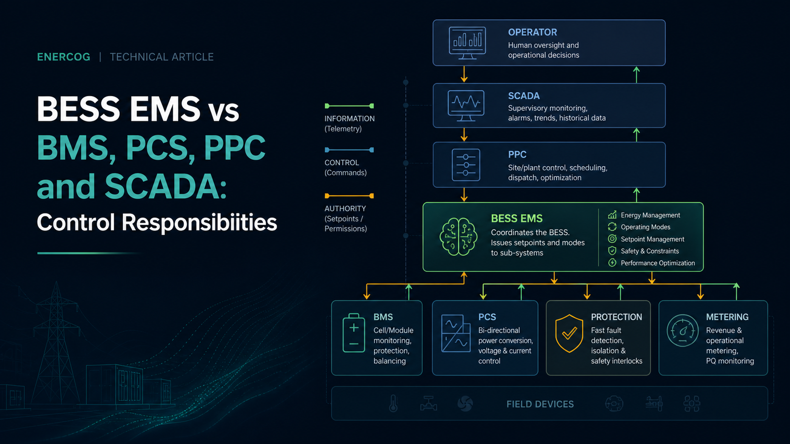
In a high-voltage battery storage plant, control authority must be strictly partitioned. Enercog’s BESS EMS supervises plant strategy while preserving the autonomous safety limits of BMS, PCS, and protection systems.
Fail-Safe Philosophy
Handling Stale Telemetry & Network Loss
When communication with a PCS, BMS, or upstream dispatcher is lost or data freshness drops below project thresholds, the BESS EMS immediately flags the condition, halts blind command replay, and transitions the plant into the pre-approved deterministic local fallback state.
Enercog Edge Controller
Coordinates plant operating modes, ToD charge/discharge schedules, contract demand limits, reserve headroom, and multi-PCS active/reactive power allocation within configured operating envelopes.
Sub-Second Closed Loop
Executes deterministic high-speed inner control loops, four-quadrant power conversion, inverter synchronization, voltage ride-through (LVRT/HVRT), and active ramp-rate enforcement at the point of common coupling.
Deterministic Battery Safety
Monitors cell-level voltages, module temperatures, string currents, and state-of-health. Owns hardware safety limits, contactor tripping, thermal runaway protection, and OEM-defined emergency safe states.
Audit & Grid Telemetry
Provides utility-grade revenue metering (ABT compliance), high-resolution historical archiving, sequence of events (SOE) recording, alarm logging, and real-time telemetry streaming to SLDC / DISCOM portals.
Hardware & Manufacturing Baseline
Modular Hardware Architecture and India-Built BESS Controller Engineering
Built on the Synapse Industrial Edge Controller platform, our BESS EMS hardware combines deterministic industrial compute, isolated communication buses, and local storage resilience.
| Architecture Parameter | Tier 1: Synapse Edge Master | Tier 2: Utility 1+1 Server Cluster* |
|---|---|---|
| Target Sizing & Scope | C&I, Microgrid, Container Gateway (<25 MW/MWh) | Utility-Scale Solar-Plus-Storage (>50 MW / 100 MWh) |
| Form Factor & Enclosure | 35mm DIN-Rail Mount / Fanless IP20/IP65 Panel | 1U / 2U 19-inch Industrial Rackmount Server |
| High Availability & Failover | Single Edge Node with Watchdog Auto-Reboot | 1+1 Hot-Standby Auto-Failover (<500ms Heartbeat) |
| Power Supply Architecture | Single 9–36 VDC Wide Input (Auxiliary Fed) | Dual Hot-Swappable AC/DC PSUs (Dual UPS Feeds) |
| Compute & System Memory | Quad-Core ARM Cortex | 2 GB / 4 GB / 8 GB RAM | Multi-Core Server CPU | 16 GB to 64 GB+ ECC RAM |
| Ethernet & Network Ports | Dual Gigabit RJ45 (Separate OT/IT Networks) | Quad Bonded Gigabit/10GbE NICs with Failover |
| Field Serial & CAN Buses | 4x Isolated RS-485/CAN (4kV Optical Isolation) | Multi-Port Optically Isolated Terminal Servers |
| Local Historian Buffering | 32–128 GB Industrial eMMC (Up to 3 Months) | High-IOPS Enterprise RAID NVMe High-Speed Logs |
| Supported Protocols | Modbus TCP/RTU, SunSpec, IEC 60870-5-104, DNP3 | IEC 60870-5-104, IEC 61850 (Client/Server), DNP3 |
Tender & Procurement Compliance
India-Built BESS EMS Engineering
Enercog develops its BESS EMS software and firmware in-house in Pune, India. Controller hardware is assembled and tested in India to meet domestic content requirements for government, utility, and PSU procurement tenders (SECI, NTPC, state DISCOMs per CEA technical standards).
Project Execution & Testing
6-Stage BESS EMS Commissioning and Acceptance Workflow
A reliable BESS EMS deployment requires structured engineering verification at every stage—from initial single-line diagram review to site acceptance testing.
01. SLD & Point List Scoping
Confirm the plant Single Line Diagram (SLD), container layout, battery chemistry, PCS register maps, POI billing meters, and utility interconnection objectives.
02. Authority & Interlock Matrix
Establish the project command matrix, defining read/write permissions, local/remote control priorities, watchdog timers, and deterministic fallback sequences.
03. OEM Protocol Mapping
Configure dedicated driver profiles for named BMS, PCS, and meter models across Modbus TCP, CANopen, IEC 60870-5-104, and proprietary vendor interfaces.
04. Factory Acceptance Testing
Simulate grid export constraints, ToD schedule switching, emergency stop triggers, and communications dropout scenarios in a controlled testbench.
05. Site Acceptance & Grid SAT
Execute live field energization, verify closed-loop ramp rate control with Solar PPC, validate POI feedback, and complete SLDC telemetry handshakes.
06. Operations & Audit Trail
Commission non-volatile telemetry archiving, continuous SoC/SoH tracking, alarm notifications, and automated reporting through Clarity UI.
Engineering & Procurement FAQ
Frequently Asked Questions About BESS EMS Architecture and Deployment
Key technical and commercial answers for renewable project developers, EPC contractors, and battery system integrators evaluating a BESS EMS.
Can the BESS EMS manage peak shaving, time-of-day scheduling, and energy arbitrage?
Yes. Enercog’s BESS EMS is engineered to execute configurable peak shaving, tariff-window scheduling, and ToD arbitrage strategies based on site Single Line Diagrams, contract demand limits, and utility tariff profiles. Commercial financial outcomes depend on project-specific tariffs and battery operating constraints.
Does the BESS EMS replace the Battery Management System (BMS) or Power Conversion System (PCS)?
No. The BESS EMS operates as a supervisory control layer. The BMS retains absolute authority over cell-level safety, thermal protection, contactor trips, and safe operating limits. The PCS retains inner closed-loop current, voltage, and frequency controls. The EMS supervises dispatch setpoints and operating envelopes within these limits.
How does the BESS EMS coordinate with a Solar Power Plant Controller (PPC)?
On solar-plus-storage hybrid plants, the BESS EMS coordinates with our Solar Power Plant Controller to manage active power curtailment, reactive power (kVAR) injection at the POI, and ramp-rate limiting, ensuring the combined plant satisfies utility interconnection requirements without conflicting commands.
What happens when communication drops between the BESS EMS, inverters, or cloud servers?
All core dispatch logic, interlocks, and control algorithms execute locally on the industrial Synapse controller without cloud dependency. If communication with inverters or BMS drops, the system halts command dispatch and activates safe fallback states. Telemetry is buffered locally for up to 3 months and replayed chronologically upon reconnection.
What is the difference between grid firming and fast grid-forming / frequency regulation?
Grid firming uses supervisory dispatch to smooth renewable intermittency and enforce ramp rate limits over seconds to minutes. Grid-forming, synthetic inertia, and sub-second primary frequency response require specialized PCS hardware capabilities and dedicated testing gates, which are evaluated separately during project scoping.
Is the BESS EMS eligible for Indian government and PSU procurement tenders?
Yes. Enercog designs and develops its BESS EMS software and firmware in India, and manufactures its controller hardware locally in Pune, India. This supports project developers requiring domestic content evidence for SECI, NTPC, state DISCOMs, and PSU tender compliance.
Engineering Consultation
Start With a Project-Specific BESS EMS Integration Review
Share your project capacity, Single Line Diagram (SLD), battery chemistry, PCS inverter models, and operating objectives with our engineering team to scope your supervisory control architecture.